• INT (interrupt module)
— Seven levels of nested interrupts
— Flexible assignment of interrupt sources to each interrupt level.
— External non-maskable high priority interrupt (XIRQ)
— The following inputs can act as Wake-up Interrupts
– IRQ and non-maskable XIRQ
– CAN receive pins
– SCI receive pins
– Depending on the package option up to 20 pins on ports J, H and P confifigurable as rising or
falling edge sensitive
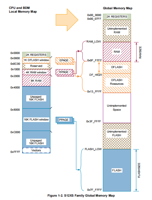
• MMC (module mapping control)
• DBG (debug module)
— Monitoring of CPU bus with tag-type or force-type breakpoint requests
— 64 x 64-bit circular trace buffer captures change-of-flflow or memory access information
• BDM (background debug mode)
• OSC_LCP (oscillator)
— Low power loop control Pierce oscillator utilizing a 4MHz to 16MHz crystal
— Good noise immunity
— Full-swing Pierce option utilizing a 2MHz to 40MHz crystal
— Transconductance sized for optimum start-up margin for typical crystals
• IPLL (Internally fifiltered, frequency modulated phase-locked-loop clock generation)
— No external components required
— Confifigurable option to spread spectrum for reduced EMC radiation (frequency modulation)
• CRG (clock and reset generation)
— COP watchdog
— Real time interrupt
— Clock monitor
— Fast wake up from STOP in self clock mode
• Memory Options
— 64, 128 and 256 Kbyte Flash
— Flash General Features
– 64 data bits plus 8 syndrome ECC (Error Correction Code) bits allow single bit failure
correction and double fault detection
– Erase sector size 1024 bytes
– Automated program and erase algorithm
– Protection scheme to prevent accidental program or erase
– Security option to prevent unauthorized access
– Sense-amp margin level setting for reads
— 4 and 8 Kbyte Data Flash space
– 16 data bits plus 6 syndrome ECC (Error Correction Code) bits allow single bit failure
correction and double fault detection
– Erase sector size 256 bytes
– Automated program and erase algorithm
— 4, 8 and 12 Kbyte RAM
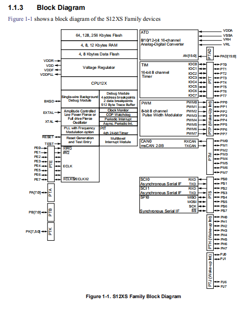
• 16-channel, 12-bit Analog-to-Digital converter
— 8/10/12 Bit resolution
— 3µs, 10-bit single conversion time
— Left or right justifified result data
— External and internal conversion trigger capability
— Internal oscillator for conversion in Stop modes
— Wake from low power modes on analog comparison > or <= match
— Continuous conversion mode
— Multiplexer for 16 analog input channels
— Multiple channel scans
— Pins can also be used as digital I/O
• MSCAN (1 M bit per second, CAN 2.0 A, B software compatible module)
— 1 Mbit per second, CAN 2.0 A, B software compatible module
– Standard and extended data frames
– 0 - 8 bytes data length
– Programmable bit rate up to 1 Mbps
— Five receive buffers with FIFO storage scheme
— Three transmit buffers with internal prioritization
— Flexible identififier acceptance fifilter programmable as:
– 2 x 32-bit
– 4 x 16-bit
– 8 x 8-bit
— Wake-up with integrated low pass fifilter option
— Loop back for self test
— Listen-only mode to monitor CAN bus
— Bus-off recovery by software intervention or automatically
— 16-bit time stamp of transmitted/received messages
• TIM (standard timer module)
— 8 x 16-bit channels for input capture or output compare
— 16-bit free-running counter with 8-bit precision prescaler
— 1 x 16-bit pulse accumulator
• PIT (periodic interrupt timer)
— Up to four timers with independent time-out periods
— Time-out periods selectable between 1 and 224 bus clock cycles
— Time-out interrupt and peripheral triggers
— Start of timers can be aligned
• Up to 8 channel x 8-bit or 4 channel x 16-bit Pulse Width Modulator
— Programmable period and duty cycle per channel
— Center- or left-aligned outputs
— Programmable clock select logic with a wide range of frequencies
• Serial Peripheral Interface Module (SPI)
— Confifigurable for 8 or 16-bit data size
— Full-duplex or single-wire bidirectional
— Double-buffered transmit and receive
— Master or Slave mode
— MSB-fifirst or LSB-fifirst shifting
— Serial clock phase and polarity options
• Two Serial Communication Interfaces (SCI)
— Full-duplex or single wire operation
— Standard mark/space non-return-to-zero (NRZ) format
— Selectable IrDA 1.4 return-to-zero-inverted (RZI) format with programmable pulse widths
— 13-bit baud rate selection
— Programmable character length
— Programmable polarity for transmitter and receiver
— Receive wakeup on active edge
— Break detect and transmit collision detect supporting LIN
• On-Chip Voltage Regulator
— Two parallel, linear voltage regulators with bandgap reference
— Low-voltage detect (LVD) with low-voltage interrupt (LVI)
— Power-on reset (POR) circuit
— Low-voltage reset (LVR)
• Low-power wake-up timer (API)
— Internal oscillator driving a down counter
— Trimmable to +/-5% accuracy
— Time-out periods range from 0.2ms to ~13s with a 0.2ms resolution
• Input/Output
— Up to 91 general-purpose input/output (I/O) pins depending on the package option and 2 input�
only pins
— Hysteresis and confifigurable pull up/pull down device on all input pins
— Confifigurable drive strength on all output pins
• Package Options
— 112-pin low-profifile quad flflat-pack (LQFP)
— 80-pin quad flflat-pack (QFP)
— 64-pin low-profifile quad flflat-pack (LQFP)
• Operating Conditions
— Wide single Supply Voltage range 3.135 V to 5.5 V at full performance
– Separate supply for internal voltage regulator and I/O allow optimized EMC fifiltering
— 40MHz maximum CPU bus frequency
— Ambient temperature range –40°C to 125°C
— Temperature Options:
– –40°C to 85°C
– –40°C to 105°C
– –40°C to 125°C